Halloween Tricker!

Halloween Tricker

What’s Halloween Tricker?

It’s a Pumpkin that can play different kinds of customised sounds while blinking. You can play a trick on your friends simply press a button on your presenter at a distance.

How does it work?

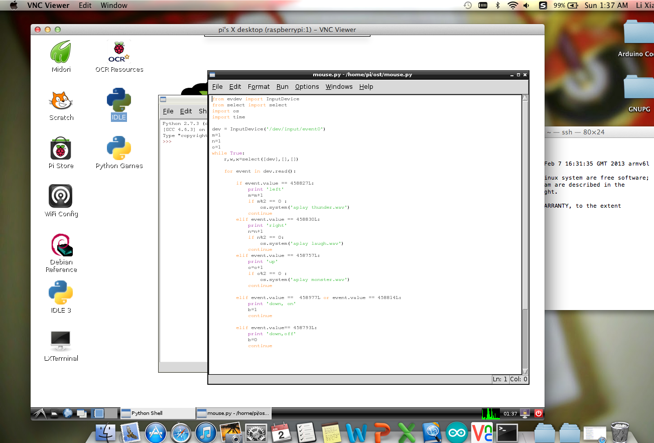
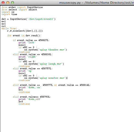
It receives the signal from a normal RF presenter with a USB receiver , then Raspberry Pi runs a python program that can read the presenter’s event value. With the help of mini speaker system, you can play any kind of sounds as long as it can be stored into the Raspberry Pi, such as screaming, laughter and some scary monster’s voice etc. Then an Arduino board is used to control a loop to blink the LEDs after connecting Raspberry Pi and Arduino using a jumper wire together.

6 presenter IMG_3236


Discussions and further improvements:

If can successfully DIY a set of LED that can be reactive with the strength of sounds output, then Arduino is not needed. After tried e analog to digital circuit, using a TIP31C transistor and 9V battery and 3.5mmP2 plug, it can only works on PC, under high volume condition. I think it’s because the audio current output of Rpi is not high enough to active transistor. For further improvements, I would like to try using a more complex circuit with more high-pass and low-pass filters, or using a NMOS transistor with a lower Vsat, or try TIP31A instead of TIP31C, which I believe will work.

Continue reading

Make music reactive LED (2nd try)

outside

This is the second try of making music reactive LED.These LED are brighter than the normal ones, more expensive of course. First we strip the 3.5mm P2 plug and solder them with wires.

p2 plug soldering strip plug

Also the transistors.About the circuit you can find it in previous post here.transistor transistor2

Well, here the problem still is : how to make LED flash to music at low volume.

Maybe next time I should design a better circuit, using capacitors and transistors together to act as a high-pass or low-pass filter, transfer analog signal to digital signal more sensitively, like some people once did Sound to Light with an microphone. Or can try using an NMOS transistor switch, choose one with a low Vsat. Some person gave an answer on Yahoo answers two years ago. Or maybe just using transistor TIP31A instead of TIP31C…maybe…

Well, just thinking of improvements.

Blinking LEDs controlled by Arduino

arduino

The picture above is the Arduino part of functions.

On the right end of breadboard, I use a wire simply represent a protection pushbutton to control the whole loop. Only if the wire is connected the LEDs can blink later.

Then leave pin 8 as input from Raspberry Pi’s GPIO. Once the pin get a HIGH impulse, LED blinking loop will be executed twice.

The code for Arduino is as follows:

const int buttonPin = 7; 
const int ledPin = 2; 
const int rpiPin = 8; //pin8 is connected to Raspberry Pi GPIO 25

int buttonState = 0; //set initial variables to 0
int rpiState = 0;
int i = 4; //set i to any contant that larger than 2, just not to execute the led blinking part.

void setup() {
   Serial.begin(9600); //open serial port, set data rate to 9600 bps
   pinMode(ledPin, OUTPUT); 
   pinMode(buttonPin, INPUT); 
   pinMode(rpiPin,INPUT) ;
}

void loop(){
   buttonState = digitalRead(buttonPin);
   rpiState = digitalRead(rpiPin);
   Serial.print(buttonState);
   Serial.print(rpiState);
   if (rpiState == HIGH ){i=1;} 
   if (buttonState == HIGH) { //just loop twice
   while (i<=2) { 
  digitalWrite(ledPin, HIGH);
  delay(100);
  digitalWrite(ledPin, LOW);
  delay(200); 
  digitalWrite(ledPin, HIGH);
  delay(400);
  digitalWrite(ledPin, LOW);
  delay(300); 
  digitalWrite(ledPin, HIGH);
  delay(200);
  digitalWrite(ledPin, LOW);
  delay(200); 
  i++;} 

else {
  digitalWrite(ledPin, LOW); 
  i=1; 
}
}

Raspberry Pi GPIO connected with Arduino

OKAY now I’m back here using Arduino to control LEDs.

I connect GPIO.25 on RPI with Arduino Pin 8. Remember to connect GND to GND to get them synchronised。While RPi is a loop sensing the RF signal input, once it need to blink LED, it generates a Pulse to Arduino. Then Arduino will execute the Blinking LED loop, at the same time RPi is playing sounds stored in its memory initially.

RPIArd

How to use RPI GPIO(General Purpose Input Output) you can find information here.

RaspberryPi-GPIO-Layout

I write a python code named pumpkin.py. Then can use

sudo python pumpkin.py

Below is the code that can perform the functions of sensing RF signals, playing sounds and ask Arduino to blink LEDs at the same time.

I add one more function, use the down button on controller to stop the loop and exit the program.

from evdev import InputDevice
from select import select
import os
import time
import RPi.GPIO as GPIO
dev = InputDevice(‘/dev/input/event0’)
m=1
n=1
o=1
b=1
GPIO.setmode(GPIO.BCM)
GPIO.setup(25,GPIO.OUT)
GPIO.output(25,GPIO.LOW)

def blink():

GPIO.output(25,GPIO.HIGH)
time.sleep(0.1)
GPIO.output(25,GPIO.LOW)
return

while b==1 :
r,w,x=select([dev],[],[])

for event in dev.read():

if event.value == 458827L:

print ‘left’
m=m+1
if m%2 == 0 :
    blink()
    os.system(‘aplay thunder.wav’)
continue

elif event.value == 458830L:

print ‘right’
n=n+1
if n%2 == 0:
    blink()
    os.system(‘aplay laugh.wav’)
continue

elif event.value == 458757L:

print ‘up’
o=o+1
if o%2 == 0 :
    blink()
    os.system(‘aplay monster.wav’)
continue

elif event.value == 458977L or event.value == 458814L or event.value== 458793L:

print ‘down, off’
b=0
continue

Make sounds reactive LEDs

TO make this LEDs blinking with music, you need these following:

1. 3.5mm P2 plug, can get from old earphones. Strip wires,twist. In my case, I found three different colour wire, black is ground, one is left channel and the other is right channel. Slip three wires, solder them with external wires, wrap each bunch with  insulating tape.

2. 3.5mm audio splitter

3.9V DC power(battery). Battery box with switch.

4.TIP 31C transistor

5. 4 * 5mm red LED

6. wire and soldering iron

circuit

Draw circuits and test before I solder all these things. Make sure the connections are right then wipe exposed wires with insulating tape. Make sure prongs and wires do not touch.

LED music test

Tidy them.

However, when I test it using PC, I need to set it almost 80% of total volume. While I test it on Raspberry Pi, it just cannot work. Guess the current from audio output not enough. BUT I HAVE SOLDERED THEM TOGETHER…..

Use RF remote control (Presenter) to play sounds on Raspberry Pi

To solve the problem of how to remote control the RPI really took a long time….Ultrasonic sensor was the first idea but it’s a little bit too expensive if just want to use it for several times. THEN  the sensibility of infrared emitter and receiver were proved to be not good enough in this case. Finally, A good Idea came out XD ~~ Making use of the Presenter with laser pointer, RF 2.4GHZ, with a USB receiver.

presenter

Then the main problem became how to get the raw data from USB devices since RPI cannot recognise it. After trying many others solutions for one day, One of the Answers made it work perfectly~

code mouse

1. FIRST, Install PIP.

sudo apt-get install python-pip python-dev build-essential 
sudo pip install – -upgrade pip 
sudo pip install – -upgrade virtualenv

2. Install Evdev Module

sudo pip install evdev

then check using     ls /dev/input

in my PC, it showes:

pi@raspberrypi ~ $ ls /dev/input/
by-id    by-path   event0   event1   mice    mouse0

then event0 is the presenter.

3. Run Python

chmod +x mouse.py

sudo python mouse.py

This is the original code of a mouse:

from evdev import InputDevice
from select import select
dev = InputDevice(‘/dev/input/event0’) # This can be any other event number. On$
while True:
r,w,x = select([dev], [], [])
for event in dev.read():
# The event.code for a scroll wheel event is 8, so I do the following
#button left 272, right 273
if event.code == 8:
print “wheel”
print(event.value)
elif event.code == 272:
print “left button”
print(event.value)
elif event.code == 273:
print “right button”
print(event.value)

This is the code of this presenter, I test it using event.value and event.code to find out what is the corresponding value of each button. Since I found that each time the button is pressed, two of the same signals was received. So I add a counter into it, and use Modulus to make sure that each press the sound also play just once. There’re other parts haven’t been added into it like LED. TO be updated~

mouse python code